. You’ve been incredibly patient: thank you. The official Raspberry Pi touch display is on sale today, priced at $60 (plus local taxes and shipping): you can buy it at the Swag Store, at RS Components/Allied Electronics and at Premier Farnell/Newark. Other sellers will be receiving stock later this week.
We gave one to Alex Eames of RasPi.TV a couple of weeks back so that he could give us one of his famously clear video introductions:
Two years ago, I began the process of looking for a simple, embeddable display for the Raspberry Pi. I honestly believed it would only take us six months from start to end, but there were a number of issues we met (and other products diverted our attention from the display – like Rev 2.1, B+, A+, and Pi 2). But we’ve finally got there, and I thought you might be interested in learning about our journey.
Display Technology
First of all, here’s an overview of the technology involved in the different types of display that the Raspberry Pi can support.
Currently the Raspberry Pi can support the following display interfaces:
HDMI
HDMI is the system we all know and love, it allows us to communicate with monitors up to 4K and has a relatively low signal swing to reduce EMI. There are lots of other very useful bits of the specification such as CEC (a communication channel between the TV and the Pi that allows us to receive input from the TV), EDID (a method of automatically identifying the different formats the TV supports) and a hotplug signal allow the Pi to know when you plug in the cable. The only problem with HDMI is that the electronics required to convert from HDMI to the native panel interface can be quite expensive.
DPI
DPI (Display Parallel Interface) is a 24-bit parallel interface with a clock and various synchronisation signals totalling 28 signals, all of which switch at a rate of around 70MHz. This interface has been phased out of tablets/phones because the electromagnetic noise created and power consumed by all those wires. Although it is possible to directly talk to a DPI display through the GPIO connector on a Raspberry Pi it would leave no GPIOs left for people to connect other HATs. DPI displays are available everywhere though, and are relatively cheap!
DSI
DSI (Display serial interface) is a high-speed serial interface based on a number of (1GBits) data lanes. The total voltage swing of the data lines is only 200mV; this makes the electromagnetic noise created and power consumed very low. Unfortunately, DSI displays are only really created and sold for special purposes (i.e. when a mobile phone manufacturer wants to make a new phone), and although they can be available to buy, manufacture of the devices is subject to the lifetime of the phone!
DBI
DBI (Display Bus Interface) is an old display technology that usually has inbuilt frame storage to reduce tearing, due to the memory and hardware it makes DBI screens expensive.
So our solution to this problem was to employ both DSI (to avoid using up all the GPIOs) and DPI (easily available screens in suitable resolutions) and a bridge chip/conversion board to convert between the two.
We got in touch with many display manufacturers to try and get a display that would tick the following requirements:
Quality colour reproductionPixel quality (sometimes you can see the individual pixel boundaries)Contrast ratioViewing angleAffordableLifetime (length of time before the display is no longer going to be manufactured)
Of course lifetime is one of the most important requirements, because if a display only has a lifetime of a few months (or the manufacturer is uninterested in guaranteeing a minimum lifetime), we would have to repeat the whole development cycle once more. So we can’t just buy a display that’s used in your standard iDevice, because it is likely to be cancelled when the iCompany decides to move to another manufacturer!
When looking for a device, we needed to look for what are termed ‘Industrial’ LCD displays. These tend to have better-quality metrics and guaranteed availability.
In the end we chose an industrial-quality display from our friends at Inelco Hunter based in the UK, who were able to create something very special:
RGB 800×480 display @60fps24-bit colourFT5406 10 point capacitive touchscreen70 degree viewing angleMetal-backed display with mounting holes for the Pi
Our first PCB to do the DSI to DPI conversion was completed back in mid-2013. The board used a Toshiba bridge chip to convert the DSI signals to DPI ones. I spent quite a bit of time getting the Raspberry Pi to talk to the bridge device, and then got it working and displaying an image (yay). We then took it to our local EMC test facility to investigate how easy it would be to pass CE and FCC electromagnetic compliance.
A little word on compliance…
When electrical currents flow around a circuit board, they create electro-magnetic fields, which can be picked up by other electronic devices. Maybe you remember what used to happen to your CRT television when your mum turned on the hoover (sorry for those of you without any experience of analogue television). This was becoming a problem for television and radio receivers; when I was a kid and plugged in my Spectrum 48K, the radio wouldn’t work properly any more. So the powers that be introduced new rules about the amount of energy a device can output at various frequencies from 25MHz up to a couple of GHz. You have to make sure your electronic devices do not cause interference, and are not susceptible to electronic interference.
The best way to reduce electromagnetic interference (EMI) is to keep your high-frequency signals short and close to a nice continuous ground plane, reduce the frequency and drive of the signals (reducing the high frequency components), and reduce the maximum swing of the signals to reduce the signal power. Looking at modern communication systems, that’s exactly what they do: for example, DSI has a signal swing of only 0.2V and only has two or four actual signal lanes.
Unfortunately, DPI is 1.8V signal swing, and although much slower, it needs 28 signal wires, meaning 28x more paths with the same edges switching up and down at the same time. This gives us an output looking something like:
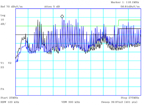
The green line is the class A line, and the black is class B (we need to reach Class B). You need to be below the black line if you want to sell the device to be used in the home.
Back to the drawing board
The next step was to understand why the EMI is so bad, so we tried redesigning the board so it looks like a HAT (it’s not actually a HAT because there is no EEPROM for device tree information), and added an Atmel device to control the power/reset and PWM for the backlight. We also went through three different iterations of adding chokes to improve the noise conducting down the power supply cable, and manipulating the route of the DPI signals to improve the path of the ground return.
In the end we did reach our goal of a class B EMC pass which is a great achievement considering where we started!
Building the display from scratch
The first displays are supplied as a kit which requires some initial construction. Alex Eames from RasPi.TV has helpfully provided a video showing how to do it.
Connecting the display
The display module integrates the LCD display with a conversion board that should be plugged into the Raspberry Pi through the display connector. Be aware that the connector is the same as the camera connector, but the two are not compatible, so be careful to correctly identify the display connector first.
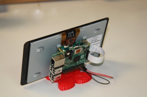
The 15-way FPC connector should already be plugged into the display conversion board with the silvered contacts face-up. You can then plug the connector into the Raspberry Pi with the silvered connectors inboard (facing towards the USB connectors).

Powering the display
There are three options for powering the display:
1) Separate power supply
Just add a separate uUSB power supply rated for at least 500mA, and plug into the display board where it says “PWR IN”.
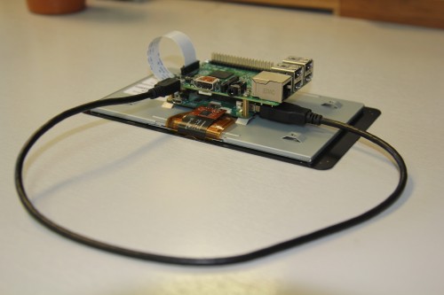
2) USB link
Attach an official 2A Raspberry Pi power supply to the display board “PWR IN” connector, then attach a standard uUSB connector from the “PWR OUT” connector to the Raspberry Pi.
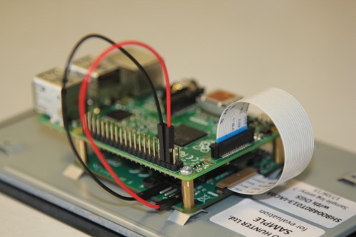
3) GPIO jumpers
Attach two of the supplied jumpers to connect 5V and GND from the Pi.
Using the display
To use the display the user just needs to do the following:
$ sudo apt-get update$ sudo apt-get upgrade$ sudo reboot
The Raspberry Pi will now automatically detect the display and use it as the default display (rather than HDMI), although HDMI will still be initialised. If you’d prefer for the HDMI display to stay as default then add:
display_default_lcd=0
to the config.txt file.
Dual display usage
It is possible to use both display outputs at the same time, but it does require software to choose the right display. Omxplayer is one application that has been modified to enable secondary display output.
To start displaying a video onto the LCD display (assuming it is the default display) just type:
# omxplayer video.mkv
To start a second video onto the HDMI then:
# omxplayer --display=5 video.mkv
Please note, you may need to increase the amount of memory allocated to the GPU to 128MB if the videos are 1080P, adjust thegpu_mem value in config.txt for this. The Raspberry Pi headline figures are 1080P30 decode, so if you are using two 1080P clips it may not play correctly depending on the complexity of the videos.
Display numbers are:
DISPMANX_ID_FORCE_LCD 4DISPMANX_ID_FORCE_TV 5DISPMANX_ID_FORCE_OTHER 6 /* non-default display */
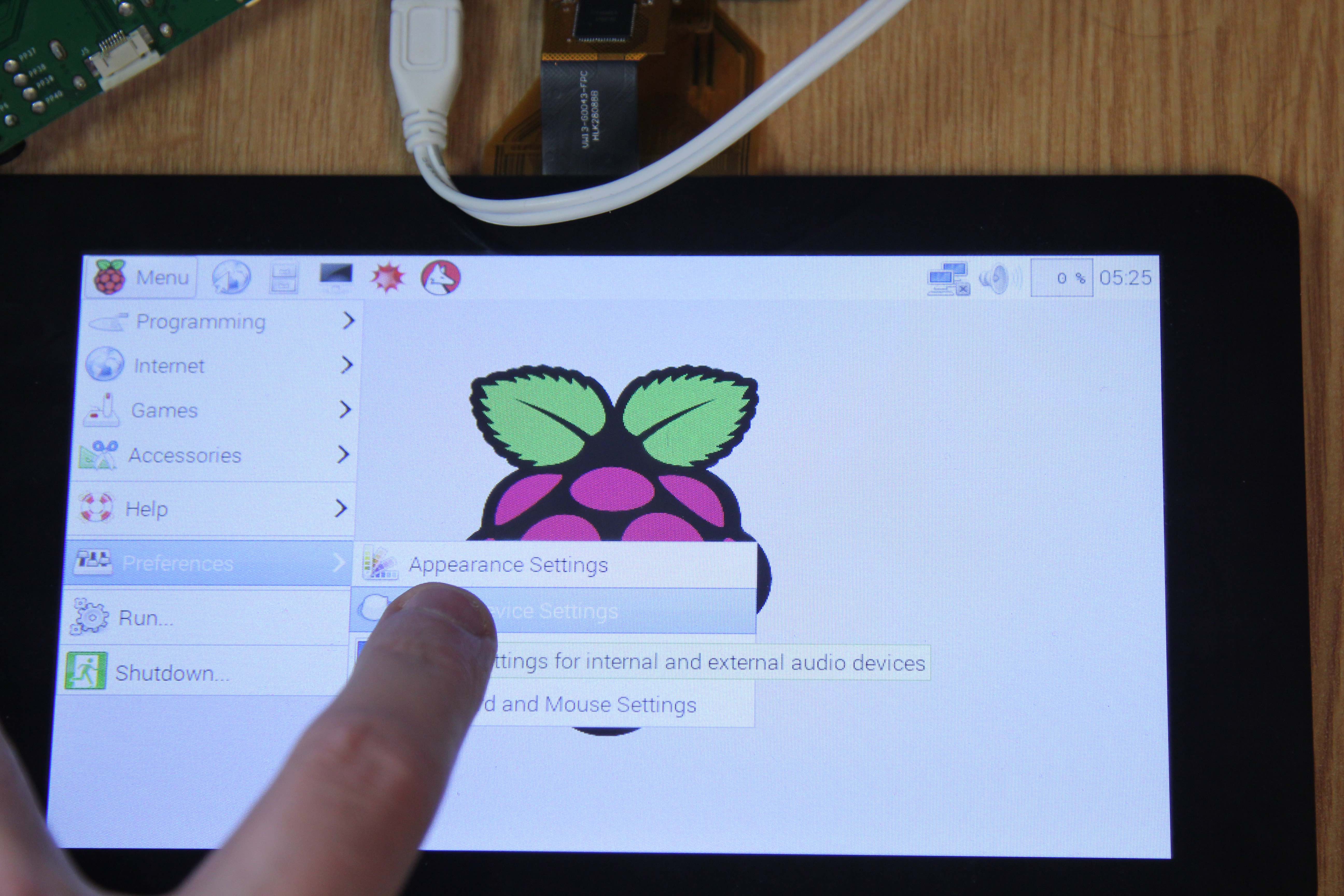
Touchscreen
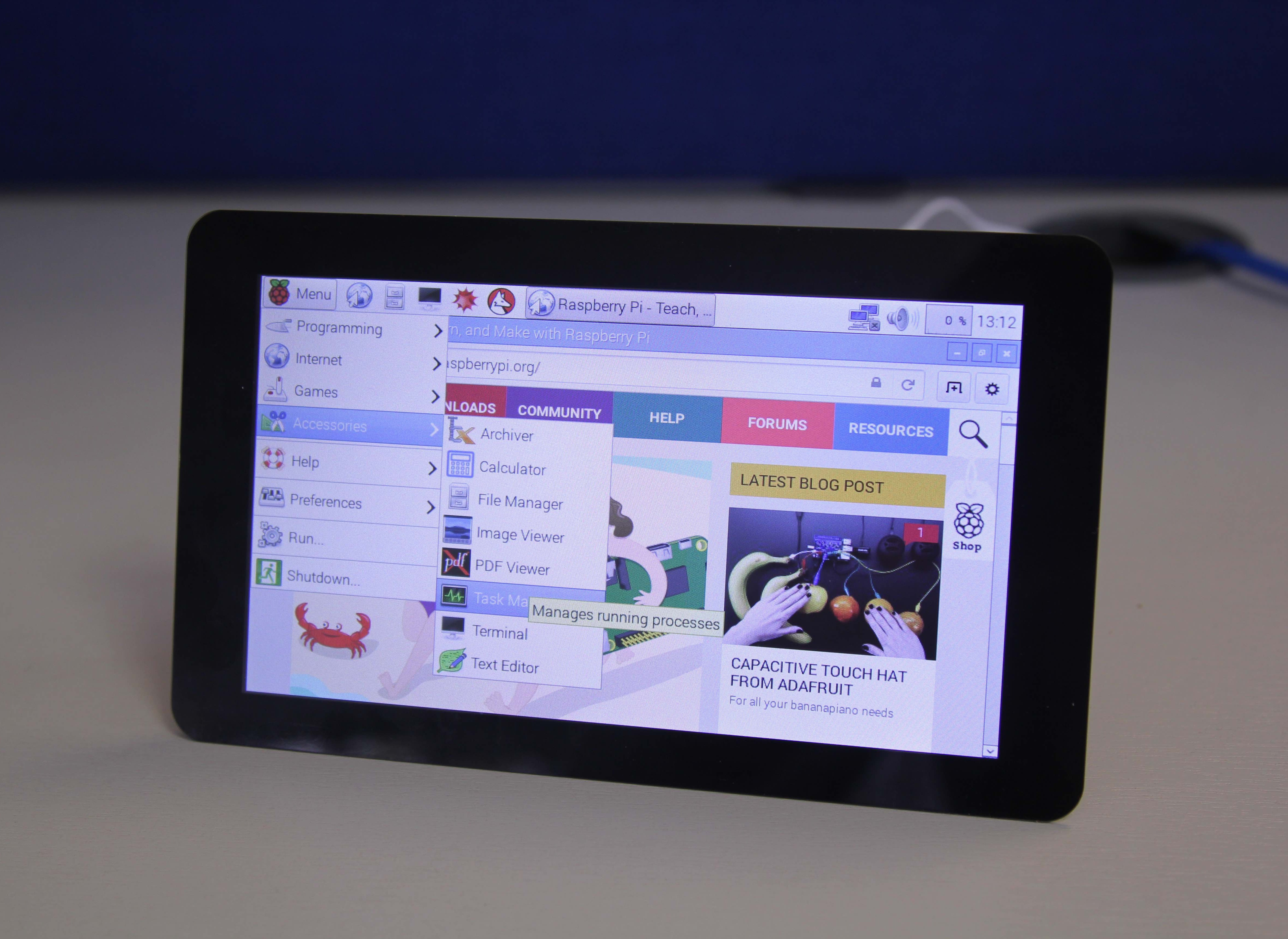
The Raspberry Pi display has an integrated 10-point touchscreen (a bit of an overkill, but it does seem to work well). The driver for this touchscreen outputs both standard mouse events and full multi-touch events, and therefore can work with X as a mouse (although not brilliantly – X was never designed to work with a touchscreen!).

Kivy
Kivy is a Python GUI development system for cross-platform applications. It is designed to work with touchscreen devices (phones and tablets), but also runs on the Raspberry Pi. To install Kivy onto your Pi follow the instructions at
http://kivy.org/docs/installation/installation-rpi.html
I’m fairly sure that these are the instructions that worked for me, although I make no claims that it’s an easy task!
This short, soundless video shows off the possibilities of Kivy with multipoint touch nicely.
Raspberry Pi’s Matt Richardson has been experimenting with using Kivy to allow the touchscreen to control Raspberry Pi’s GPIO, and vice versa:
From the videos you can see how capable the interface is. I’m in the process of developing a touchscreen application for an installation at home to control a safety and heating monitoring system, so you’ll probably hear more about that at some point!
Last of all, if you’d like a stand for your display, you could do a lot worse than to take a look at the 3D-printed one that Matt Timmons-Brown has designed; we like it a lot. You’ll find his model on Thingiverse.
Have fun, and make something awesome!
Gordon


No comments:
Post a Comment